

Case Study · Medical Imaging
MRI Cooling System Failure: The Chiller Never Alarmed
A hidden hydraulic restriction reduced cooling-water flow to a high-use MRI—even while the process chiller stayed online, maintained leaving-water temperature, and showed no refrigeration fault.
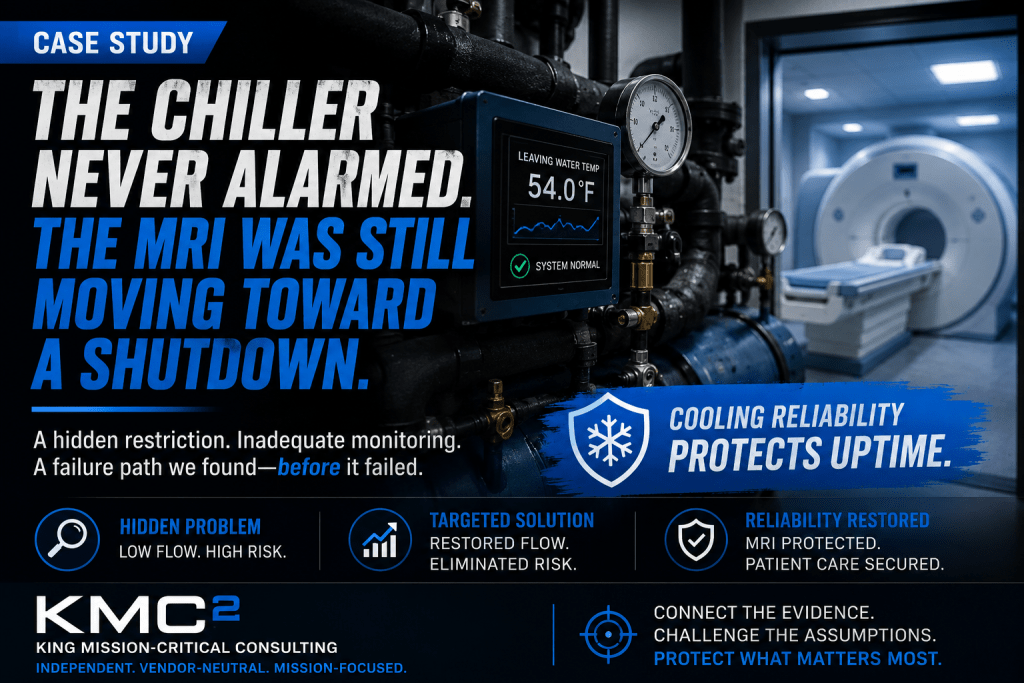
Intermittent MRI water-flow alarms during long scans
Normal chiller status suggested the system was healthy
Hydraulic flow restored without replacing the chiller
An MRI cooling system failure does not always begin with a chiller trip, failed compressor, or high-temperature alarm.
In this case, the process chiller remained online. It maintained its leaving-water temperature. Both refrigeration circuits were available, and the controller showed no active fault.
From the mechanical room, the cooling system appeared normal. At the MRI, the available cooling margin was steadily disappearing.
This MRI cooling system case study shows why producing cold water and delivering adequate cooling are not the same thing.
Case Study at a Glance
High-use 1.5-tesla MRI at a regional outpatient imaging center
Intermittent primary-water-flow alarms during longer imaging procedures
Chiller online, acceptable leaving-water temperature, no refrigeration fault
Restricted strainer plus excessive bypass flow reduced water reaching the MRI
Remove the restriction, rebalance the bypass, restore flow, and test under sustained load
Stable MRI cooling restored without replacing the chiller
The MRI Cooling System Looked Healthy
A regional outpatient imaging center operated a high-volume 1.5-tesla MRI system six days a week.
The dedicated process chiller received routine preventive maintenance. Service records showed no unresolved refrigeration faults, and the chiller controller consistently displayed an acceptable leaving-water temperature.
Then the MRI recorded two intermittent primary-water-flow warnings within several weeks.
Both warnings cleared before a service technician arrived. The chiller remained online, and the MRI returned to normal operation after a reset.
The initial conclusion was that the scanner had experienced a nuisance alarm or a momentary sensor issue. That appeared reasonable because nothing in the mechanical room indicated an active MRI chiller failure.
It was also the wrong conclusion.
The question was whether the complete cooling system could deliver enough usable cooling to the MRI during sustained operation.
The Warning Pattern Exposed a Larger Risk
The third warning occurred near the end of a long, thermally demanding imaging sequence.
The scan was completed, but the MRI cooling-water temperature remained elevated longer than expected. The equipment-room temperature also increased slightly. Once again, the process chiller had not alarmed.
The warnings were not random. They occurred during longer studies that placed a sustained thermal load on the MRI cooling system. Shorter scans did not create enough heat to expose the problem.
The cooling system appeared stable under light load.
Its operating margin disappeared as the load increased.
The Monitoring System Had a Critical Blind Spot
The MRI was supported by a dedicated air-cooled process chiller with approximately 45 kilowatts of nominal cooling capacity.
What the System Included
- Two refrigeration circuits
- Lead and standby pumps
- Supply and return piping
- A field-installed Y-strainer
- A minimum-flow bypass
- Basic building-system monitoring
What Was Not Monitored
- Actual water flow to the MRI
- Differential pressure at the scanner
- Pressure drop across the strainer
- MRI return-water temperature
- Water recirculating through the bypass
- Hydraulic margin during high load
The facility could confirm that the chiller was running. It could not confirm that the MRI was receiving the cooling flow it required.
Connecting the Evidence
The investigation evaluated the complete cooling system rather than treating the chiller as an isolated piece of equipment. The evidence included MRI alarm and event records, chiller-controller history, preventive-maintenance reports, pump amperage readings, supply- and return-water temperatures, pressure measurements at the chiller and MRI, strainer differential pressure, bypass-valve position, and the imaging schedule associated with each warning.
A clear pattern emerged: the MRI warnings appeared when sustained imaging activity placed the greatest demand on the cooling system.
Two Reasonable Assumptions Proved Incorrect
Assumption 1: The Chiller Was Too Small
The installed chiller had sufficient nominal capacity for the MRI. It produced water within the expected operating range, and its compressors responded normally as the load changed.
Replacing the chiller would not have corrected the actual failure path because the problem occurred after the water left the chiller.
Assumption 2: Cold Water Proved Adequate Cooling
Field measurements showed that approximately 14 gallons per minute were reaching the MRI during a high-demand operating period.
Earlier commissioning information indicated that the system had historically operated near 22 gallons per minute under comparable conditions.
Chiller leaving-water temperature
Reduced flow reaching the MRI
Flow after correction
During ordinary imaging activity, the reduced flow was just sufficient to carry the load. During longer sequences, MRI return-water temperature climbed from approximately 63°F toward 69°F. The scanner recognized the loss of cooling margin and generated a primary-water-flow warning.
The chiller controller saw an acceptable leaving-water temperature.
The MRI experienced inadequate heat removal.
Both observations were technically correct. They described two different parts of the same system.
Why the Condition Threatened MRI Uptime
The MRI warning was not the underlying problem. It was the final visible indication of a deteriorating cooling path.
Had the restriction continued to increase, the facility faced several credible consequences:
- Interrupted or aborted patient scans
- Protective shutdown of MRI subsystems
- Extended recovery and functional testing
- Emergency manufacturer service
- Cancelled or rescheduled procedures
- Increased thermal stress on water-cooled components
- Reduced tolerance for another equipment failure
Redundant components did not create a redundant cooling system.
Both refrigeration circuits and both pumps depended on the same restricted distribution path.
Related reading: When the Chiller Trips, the MRI Clock Starts Ticking.
Why This Matters to Imaging Centers and Health Systems
Medical imaging cooling sits at the intersection of clinical operations, facility infrastructure, equipment service, and patient scheduling. A problem that appears small in a mechanical room can create a disproportionate operational effect when it threatens a scanner booked throughout the day.
For imaging administrators, the important issue is not merely whether the chiller has been maintained. It is whether the complete cooling path has enough verified margin to support the actual scanning schedule, including long and thermally demanding studies.
For facility and reliability teams, chiller status alone is an incomplete performance indicator. Supply temperature, return temperature, flow, differential pressure, strainer condition, bypass position, pump availability, and recovery behavior must be interpreted as one system.
MRI service provider
May verify the scanner and its internal alarms, but not the complete external hydraulic path.
Chiller contractor
May verify refrigeration and leaving-water temperature, but not cooling delivery at the MRI.
Controls contractor
May verify available points, but unmonitored flow and differential pressure remain invisible.
Facility team
May respond correctly to alarms while lacking the measurements needed to detect gradual loss of margin.
None of those checks independently proves that adequate cooling reaches the MRI under sustained load. The same principle applies wherever cooling failure can interrupt clinical work: MRI, computed tomography, positron emission tomography, linear accelerators, and other high-value medical systems. Equipment-specific requirements differ, but cooling must be verified at the protected load—not inferred from the condition of one upstream component.
Prioritizing the Corrective Response
Restore the Hydraulic System
- Clean the Y-strainer
- Flush the affected piping section
- Inspect the removed debris
- Rebalance the minimum-flow bypass
- Verify pump rotation and amperage
- Confirm standby-pump operation
Verify Under Real Load
- Observe sustained high-demand imaging
- Verify flow and supply/return temperatures
- Confirm refrigeration staging
- Test standby-pump operation
- Document recovery after load decreases
Close the Monitoring Gap
- Monitor MRI supply and return temperatures
- Monitor actual flow and differential pressure
- Trend strainer differential pressure
- Confirm pump and standby status
- Set early-warning thresholds
Performance Verification
Cleaning the strainer and rebalancing the bypass restored water flow from approximately 14 gallons per minute to approximately 22 gallons per minute. The cooling system was then observed through several sustained, high-demand imaging sequences.
Supply-water temperature remained stable, MRI return-water temperature peaked near 63°F, cooling-water flow remained consistent, the standby pump was functionally tested, both refrigeration circuits staged normally, and no primary-water-flow warning occurred. The system also recovered predictably after the load decreased.
This provided more meaningful evidence than simply restarting the equipment and confirming that the chiller ran. It demonstrated that the complete cooling path could support the MRI under the conditions that had previously exposed the problem.
Condition-Based Maintenance and Early Warning
The original monitoring strategy could identify a complete chiller failure. It could not identify a gradual loss of cooling delivery.
The improved MRI cooling system reliability plan included MRI supply-water temperature, return-water temperature, actual cooling-water flow, differential pressure at the MRI and across the strainer, pump operating status, and standby-pump availability.
Alarm thresholds were structured to provide warning before the MRI reached its internal protective limits. Strainer maintenance was also changed from an arbitrary calendar schedule to a condition-based approach using differential pressure.
MRI Cooling System Failure Corrected Without Chiller Replacement
The existing chiller did not need to be replaced.
The facility corrected a hydraulic problem that was nearly invisible when the cooling system was evaluated one component at a time.
The immediate result was restored water flow and stable MRI cooling during high-demand operation. The more important result was removing a credible path to an unplanned MRI shutdown before the protective warning became a complete equipment outage.
A focused hydraulic correction and monitoring improvement removed a verified threat to equipment availability, patient scheduling, and imaging operations.
Five Lessons for MRI Cooling System Reliability
A Running Chiller Does Not Prove the MRI Is Protected
Chiller status describes conditions at the chiller, not how much usable cooling reaches the MRI.
Redundancy Must Be Evaluated End to End
Two compressors or pumps provide limited protection when both depend on the same restricted path.
Gradual Restrictions Can Be Difficult to Find
A partially restricted strainer can keep a system operating while its reliability margin disappears.
Testing Must Reproduce Real Operating Conditions
The failure path only became visible during sustained, high-demand MRI operation.
The Earliest Warning May Be Outside the Chiller
Flow, differential pressure, return-water temperature, pump behavior, and recovery time can expose a problem before the chiller alarms.
A Practical MRI Cooling-System Review
A useful reliability review should follow the cooling path from the source to the protected equipment. The purpose is not to impose one universal set of values. MRI manufacturer requirements, project design documents, and the engineer of record remain controlling. The purpose is to verify that the installed and operating system can meet those requirements under realistic conditions.
Confirm Requirements
- Identify current requirements for temperature, flow, pressure, water quality, alarms, and operating range.
- Confirm that the documents match the installed MRI model and site configuration.
- Compare requirements with design, commissioning records, and current setpoints.
Measure Delivered Cooling
- Measure supply and return temperatures near the MRI connection.
- Verify flow and differential pressure at representative load.
- Measure pressure loss across strainers and other restrictions.
- Check whether bypass flow is diverting water from the scanner.
Test Failure Response
- Functionally test lead and standby pumps where permitted.
- Confirm refrigeration staging and recovery after load.
- Verify early warning before the MRI reaches a protective limit.
- Document the facility response to abnormal trends and alarms.
The result should be a defensible picture of the complete system—not a collection of separate service reports that leave the interfaces unexamined.
MRI Cooling System Failure: Common Questions
Can an MRI Cooling System Fail Without a Chiller Alarm?
Yes. A chiller can maintain its leaving-water temperature while the MRI receives inadequate water flow. A downstream restriction, incorrectly adjusted bypass, distribution problem, or deteriorating pump performance can reduce heat removal at the scanner without creating a refrigeration alarm. Chiller status confirms that cold water is being produced. It does not prove that the complete MRI cooling system is delivering the required flow and operating margin at the protected equipment.
What Measurements Can Reveal a Developing MRI Cooling Problem?
The most useful measurements normally include supply- and return-water temperature at the MRI, actual cooling-water flow, differential pressure at the scanner, pressure drop across strainers, bypass flow or valve position, and pump operating status. These measurements should be evaluated together and under representative operating load. Alarm limits and acceptable ranges must be verified against the current MRI manufacturer’s requirements, cooling-system design, and engineer of record.
Why Don’t Redundant Pumps and Refrigeration Circuits Eliminate the Risk?
Redundant components do not provide complete system redundancy when they share the same failure path. Two pumps may still depend on one restricted strainer. Two refrigeration circuits may still deliver water through the same improperly balanced bypass and distribution piping. MRI cooling system reliability must be evaluated from the chiller through the complete hydraulic path to the scanner—not simply by counting compressors, pumps, or other redundant components.
How Should MRI Cooling Performance Be Verified After Corrective Work?
The cooling system should be tested under sustained conditions representative of the operating load that previously exposed the problem. Verification should document cooling-water flow, supply and return temperatures, differential pressure, pump operation, refrigeration staging, alarm response, and recovery after the load decreases. Standby equipment and transfer sequences should also be functionally tested where applicable. A successful restart proves that equipment can run; sustained-load testing provides stronger evidence that the complete MRI cooling system can support actual imaging operation.
Reliability Problems Often Develop Between Responsibilities
The MRI provider evaluates the scanner. The chiller contractor evaluates the refrigeration equipment. The controls contractor evaluates available control points. The facilities team responds to alarms.
Each group may perform its assigned work correctly while the complete system continues moving toward failure.
Connect the evidence.
Challenge the assumptions.
Isolate the credible failure path.
Prioritize the response.
The objective is not to blame a component or recommend unnecessary replacement equipment. The objective is to determine what the cooling system is actually doing, what conditions could interrupt the protected operation, and which practical actions will reduce that risk.
Explore additional cooling reliability case studies involving mission-critical systems.
Is Your MRI Cooling System Actually Proven?
A clean service report and a running chiller do not necessarily mean the complete MRI cooling system has been proven under real operating conditions.
KMC² provides independent, vendor-neutral reviews of cooling systems supporting MRI, CT, PET, linear accelerator, and other high-value medical equipment.
Case study disclosure: This representative case study is based on established medical-imaging cooling requirements, common hydraulic failure modes, and diagnostic methods used in mission-critical cooling analysis. Facility-identifying information is not included. Temperature, flow, water-quality, and redundancy requirements are equipment-specific and must be verified against current MRI manufacturer documentation and the engineer of record. See the GE HealthCare site-planning resource as one manufacturer reference.