

Thermal Control Plane for AI Data Center Cooling
Beyond the Cold Plate examines why GPU and SoC cooling must be evaluated by thermal response, observability, fluid integrity, and recovery—not only by steady-state heat-removal capacity.
Public-information and independence note
This independent engineering analysis is based on publicly available research, technical standards, published studies, and general engineering principles. It does not describe or rely on confidential information, internal practices, customer data, or nonpublic observations from any employment or consulting engagement. The scenarios are hypothetical and are intended to illustrate design, controls, commissioning, and reliability considerations.
AI data center cooling is being pushed closer to higher-power silicon, with less thermal margin and faster workload changes.
A rack or CDU can look healthy in aggregate while one branch, package, or device is already losing protected thermal margin.
A thermal control plane should connect workload, silicon, rack hydraulics, CDU behavior, fluid condition, and facility heat rejection.
Why the thermal control plane matters now
A thermal control plane is becoming necessary because AI data center cooling is no longer a room-level utility operating independently from the compute it protects. Cooling is moving from the room to the rack, from the rack to the package, and in emerging designs, toward the silicon itself.
That movement improves heat capture, but it also shortens the distance between a local fluid problem and a compute-performance problem. A partially restricted passage, an incorrect valve position, a degrading interface, a drifting sensor, an air pocket, a loaded filter, or an unstable control response can reduce local protection long before the central plant recognizes a meaningful change.
This is why the traditional capacity question—Can the system remove the design heat load?—must be supplemented by a dynamic question: Can the system recognize degradation, preserve thermal margin, and recover before useful compute is lost?
- How quickly can a workload change compared with the response of the cooling controls?
- Can total rack flow conceal a local branch restriction?
- Does an acceptable junction temperature indicate healthy cooling, or successful silicon throttling?
- How much time remains after cooling performance begins to deteriorate?
- Can the workload scheduler participate in thermal protection before a hard limit is reached?
Cooling capacity describes what a system can remove at a defined condition. Thermal resilience describes whether it can continue protecting compute while conditions are changing.
For silicon and package teams
The challenge is to connect power density, hotspot location, package resistance, coolant delivery, and throttling behavior on a common time base.
For data center teams
The challenge is to prove that rack distribution, CDU controls, fluid condition, and heat rejection respond quickly enough to protect the intended workload.
The thermal control plane: a chip-to-plant operating model
The thermal control plane is not one controller, one protocol, or one dashboard. It is the connected information and decision layer that interprets the complete cooling chain as a single service to the compute load.
Most liquid-cooled environments already collect substantial information. The problem is fragmentation. Workload telemetry, device temperatures, branch conditions, CDU status, fluid data, and plant operation may be owned by different teams, sampled at different rates, and stored in systems that do not share an event chronology.
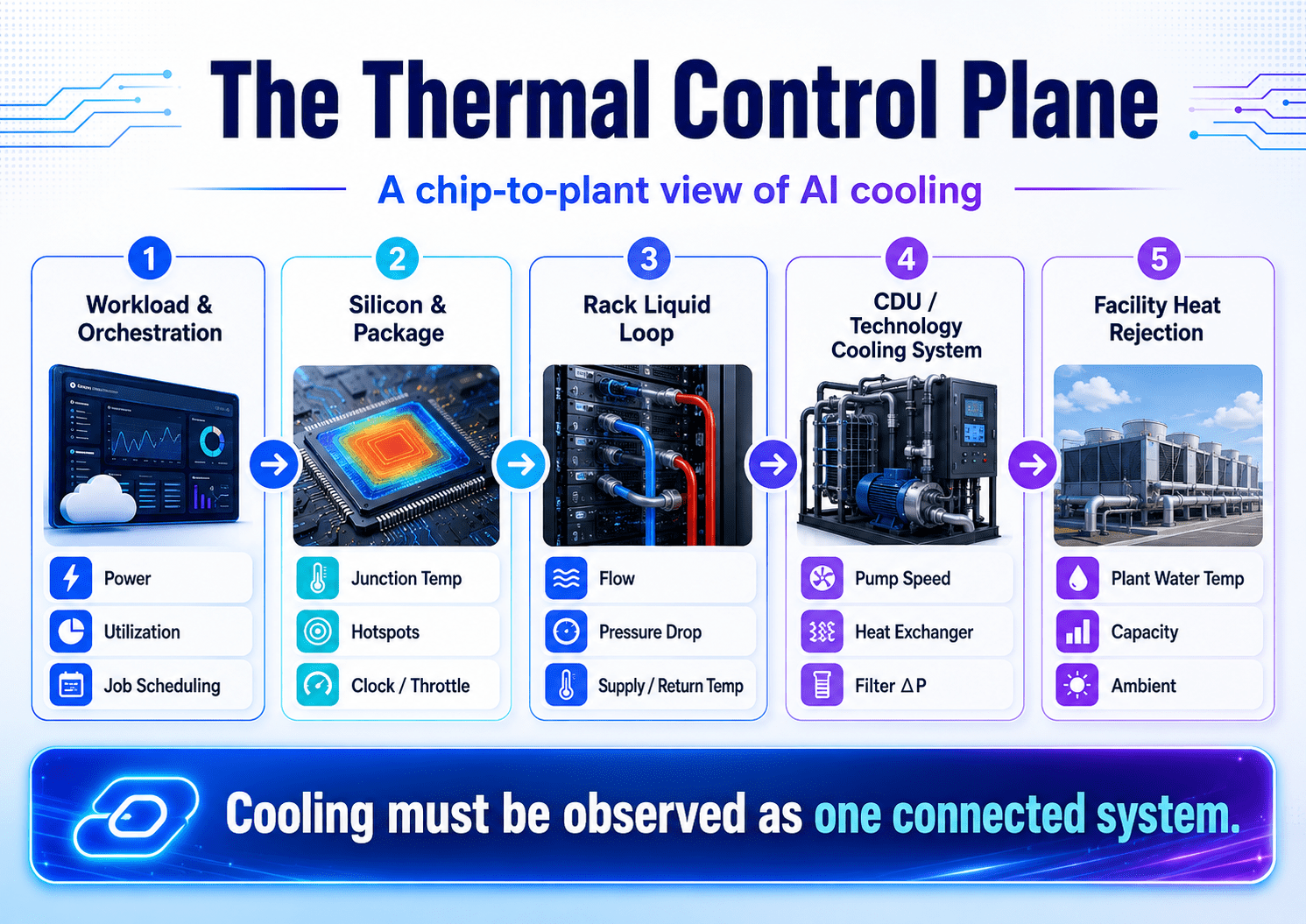
Power, utilization, job timing, load ramps, and the ability to delay or relocate work.
Junction temperature, hotspot behavior, memory temperature, clock state, and throttling.
Branch flow, differential pressure, supply and return temperature, valves, and leak status.
Pump speed, heat-exchanger approach, filtration, fluid condition, reservoir, and control mode.
Plant-water temperature, available capacity, ambient conditions, economizer state, and redundancy.
The thermal latency mismatch
The workload, silicon, liquid loop, CDU, and heat-rejection plant do not respond at the same speed. A synchronized compute load can rise rapidly. The silicon and package react first. Local coolant conditions follow. Pumps, valves, heat exchangers, chillers, dry coolers, and other facility equipment respond through their own physical inertia and control sequences.
The thermal control plane must therefore manage a response-time problem, not merely a capacity problem. It needs enough data resolution to detect a meaningful transient, enough context to diagnose it, and enough remaining thermal margin to support a corrective action.
Practical implication: if the combined detection and response time is longer than the available thermal ride-through, the silicon must throttle, derate, or shut down before the cooling system can restore the required margin.
What a useful thermal control plane should do
Create a common time base
Synchronize workload, silicon, rack, CDU, and plant events closely enough to reconstruct cause and effect.
Compare measurements with physics
Use energy balance, hydraulic relationships, and expected thermal resistance to identify disagreement among sensors.
Estimate what cannot be measured directly
Use virtual sensors and validated models to infer branch health, remaining margin, and likely failure location.
Coordinate the response
Connect mechanical controls, facility operations, and workload actions rather than allowing each system to respond in isolation.
How the thermal control plane changes by cooling architecture
Direct-to-chip cooling, immersion cooling, and emerging microfluidic approaches are often presented as competing technologies. A more useful comparison is how each architecture changes heat capture, serviceability, fluid stewardship, observability, and transient response.
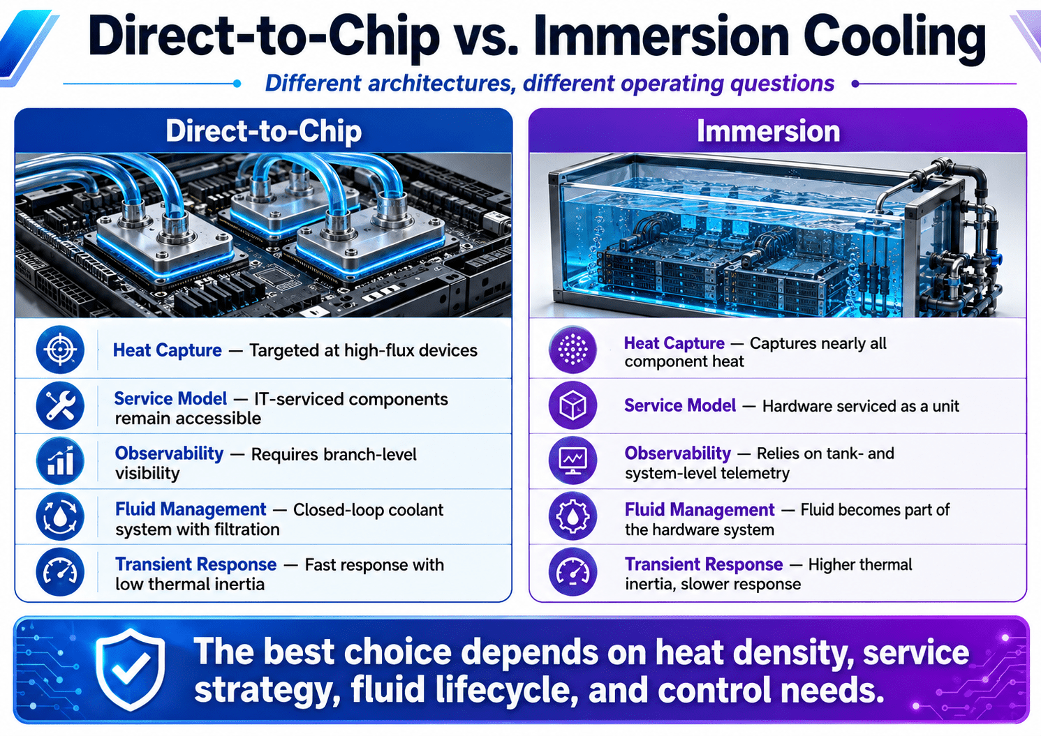
Direct-to-chip emphasizes
- Branch-level visibility and balance
- Cold-plate pressure drop and local temperature rise
- Quick-disconnect, hose, valve, and manifold integrity
- Package contact and thermal-interface performance
- Fast response with relatively low local thermal mass
Immersion emphasizes
- Fluid compatibility with the complete hardware material set
- Tank-level and local component flow distribution
- Fluid condition, contamination, filtration, and service history
- Different maintenance and replacement workflows
- Greater bulk thermal inertia but potentially different local response
Microfluidics creates an observability paradox
Moving coolant closer to the silicon can reduce thermal resistance and target hotspots more precisely. At the same time, smaller passages can increase sensitivity to particles, deposits, fluid stability, channel variation, and local maldistribution.
The observability paradox is that the cooling path becomes more intimate while the most important passages become harder to inspect directly. The thermal control plane may need to infer internal health from the relationship among power, junction temperature, coolant inlet temperature, flow, differential pressure, and transient response.
Potential health indicator: if effective thermal resistance rises under comparable load and inlet conditions, the system may be experiencing a change in internal flow distribution, surface condition, package contact, fluid properties, or sensing accuracy.
Fluid lifecycle belongs inside the operating model
Fluid should not be treated as an anonymous utility that remains unchanged after installation. The thermal control plane should retain enough lifecycle context to connect changes in thermal behavior with filtration history, component changes, fluid additions, contamination events, operating-temperature exposure, and chemistry or dielectric-property trends appropriate to the selected coolant.
A practical coolant passport can record the approved formulation, lot, initial acceptance data, compatible materials, hours of service, laboratory results, filter events, repairs, top-offs, leaks, and final disposition. That record becomes especially important when hardware from multiple suppliers shares one fluid volume.
What silicon and package teams need from the thermal control plane
For silicon development, a thermal control plane can provide more than a facility-temperature feed. It can establish whether package behavior, fluid delivery, and compute performance remain connected in the way the design assumed.
A steady-state maximum temperature is not enough. Two devices can reach similar temperatures while following very different paths. One may have stable cooling and adequate margin. The other may already be reducing clock frequency or redistributing workload to stay within limits.
Spatial behavior
Track hotspot location, chiplet-to-chiplet spread, memory temperature, and whether temperature nonuniformity changes with workload placement.
Dynamic behavior
Measure temperature rate of rise, time to peak, settling time, throttling onset, and recovery after a controlled load transition.
Fluid relationship
Correlate device power with inlet temperature, local flow, differential pressure, coolant rise, and calculated heat removal.
A proposed microchannel or cold-plate health index
One useful development direction is a health index based on several relationships rather than one alarm threshold. The index could compare current behavior with a commissioned baseline or validated model and flag a loss of expected thermal performance before the device reaches its absolute temperature limit.
- Device power versus junction and hotspot temperature
- Inlet temperature versus junction temperature
- Flow versus differential pressure
- Liquid-side heat removal versus reported device and tray power
- Temperature rate of change following a controlled workload pulse
- Clock, throughput, and throttle state during the same event
Development risk: a cooling design can appear successful if the silicon quietly protects itself. Temperature, power, clock, workload throughput, and fluid conditions should be evaluated together.
What data center teams need from the thermal control plane
Data center teams need to know more than whether the CDU is running or whether facility-water temperature is within a broad limit. They need to know whether the complete thermal service remains capable of protecting the contracted or intended workload with the required redundancy intact.
This requires clear ownership boundaries. The server team may own BMC telemetry. The rack team may own manifolds and leak detection. The CDU vendor may own equipment controls. Facilities may own heat rejection. Operations may own the workload response. Commissioning must prove that the interfaces among those groups work under realistic disturbances.
Observability requirements
- Common timestamps and adequate sampling intervals
- Branch or device visibility where aggregate values can conceal failure
- Fluid-condition records connected to operating events
- Throttling and useful-compute indicators, not temperature alone
Control requirements
- Defined fail-safe states for sensor and communications loss
- Validated pump, valve, and heat-rejection sequences
- Clear response when redundancy has been lost but cooling remains available
- Workload reduction or relocation before hard protection thresholds
The thermal one-line
Electrical systems use one-line diagrams to communicate sources, distribution paths, protective devices, and redundancy. Liquid-cooled AI installations would benefit from a comparable thermal one-line that shows every critical dependency from the workload and silicon through the rack, CDU, facility loop, and final heat sink.
- Critical devices and branches
- Isolation and bypass paths
- Pumps, filters, heat exchangers, reservoirs, and control valves
- Measurement points and alarm dependencies
- Normal, degraded, and emergency operating states
- Where a single failure can remove observability or usable redundancy
Thermal ride-through: the time dimension of the thermal control plane
Mission-critical facilities routinely quantify electrical ride-through. Owners know how long a UPS can support a defined load and how quickly generators and transfer systems must respond. Liquid-cooled AI infrastructure needs a comparable thermal answer.
Thermal ride-through is the time during which the compute can remain inside its temperature and performance envelope after cooling performance begins to deteriorate. It changes with workload, fluid temperature, system volume, local thermal mass, chip limits, control speed, and cooling architecture.
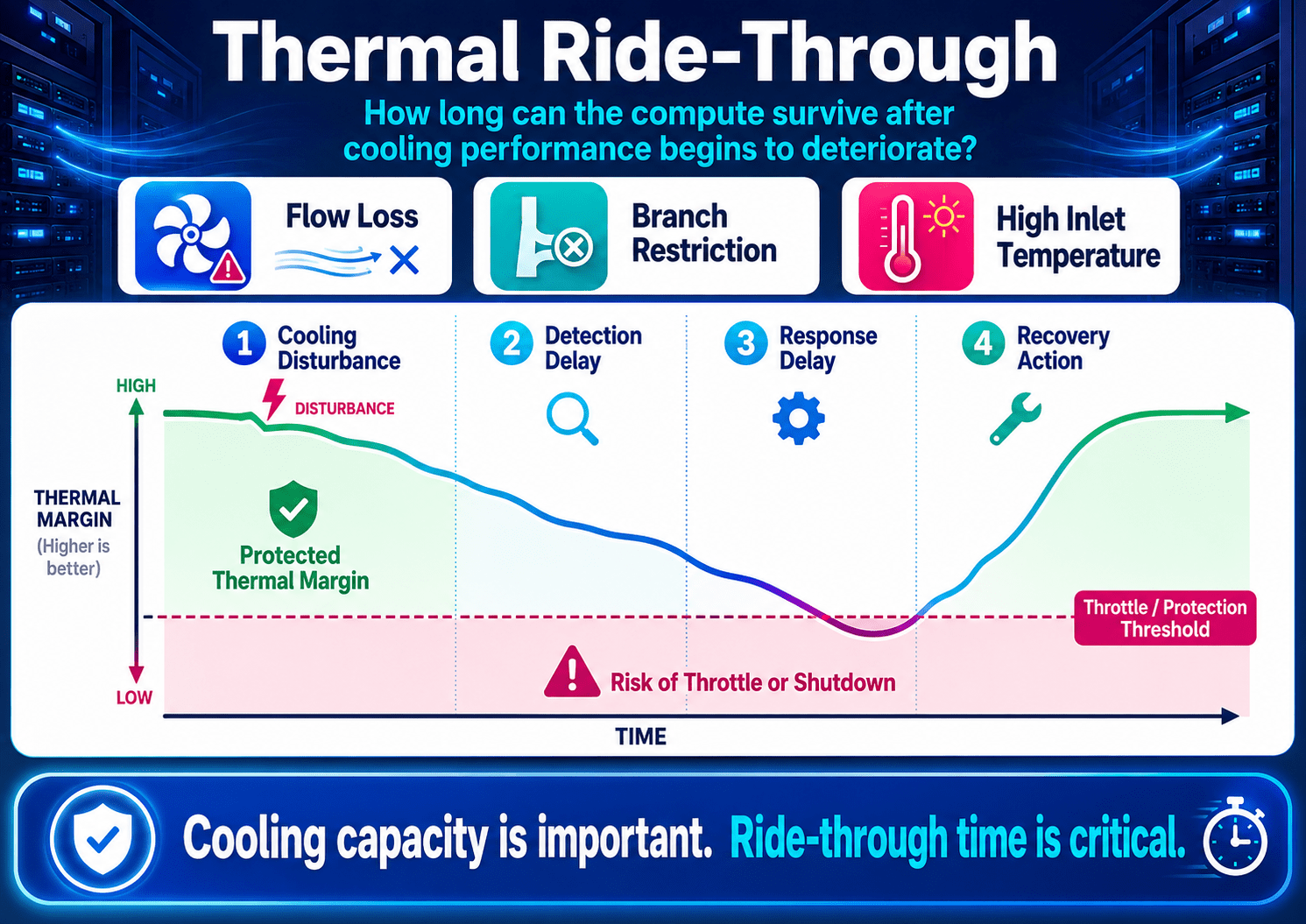
Disturbance
Flow loss, restriction, elevated inlet temperature, pump degradation, or plant-side limitation begins.
Detection
The thermal control plane recognizes that measured behavior has departed from the expected state.
Decision
Controls or operations identify the safest response and determine whether mechanical action is fast enough.
Recovery
Flow, heat rejection, redundancy, or workload is adjusted before the remaining thermal margin is exhausted.
Key distinction: a cooling system can remain “on” after thermal availability has been lost. Equipment uptime, protected workload, required redundancy, and remaining ride-through should not be treated as the same condition.
Thermal availability
A useful definition of thermal availability is the percentage of required operating time during which the compute system can sustain its agreed workload inside temperature and performance limits, while maintaining the specified cooling redundancy, without emergency intervention.
This makes the thermal control plane accountable to useful compute rather than only to equipment status. A pump can be running while a branch is underflowing. A rack can be online while throttling reduces output. A CDU can remain available after the system has lost the redundancy needed to survive the next credible failure.
Six ideas worth testing in the next generation of AI cooling
The following concepts are not proposed as finished standards. They are practical research and commissioning directions that could improve the usefulness of a thermal control plane across silicon development, system integration, and data center operations.
Build a thermal ride-through curve
Measure the seconds available before throttling or protection across multiple loads, inlet temperatures, and failure modes.
Use active thermal fingerprinting
Apply a controlled workload pulse and record the synchronized response from device power through final heat rejection.
Make cooling workload-aware
Use job timing and expected load as feed-forward information so cooling can be staged before the heat arrives.
Create physics-based virtual sensors
Combine energy balance, hydraulic relationships, and baselines to detect conditions that cannot be measured directly.
Track fluid condition in the operating record
Connect filtration, chemistry, dielectric properties, contamination, and service events with observed thermal performance.
Commission the complete control plane
Test the interfaces among server telemetry, rack controls, CDU logic, facility systems, and workload response—not only individual devices.
Active thermal fingerprinting
A controlled workload pulse can serve as a repeatable thermal input. During an approved commissioning or maintenance window, the test can capture device power, junction temperature, clock state, inlet and outlet temperature, local flow, differential pressure, pump response, CDU operation, and plant conditions on one timeline.
The resulting signature becomes a thermal fingerprint. Repeating the same test later can reveal a developing restriction, air accumulation, heat-exchanger fouling, pump degradation, fluid-property change, sensor drift, package-interface deterioration, or control-loop instability before the system reaches a conventional alarm limit.
Why it is useful: steady-state testing proves one operating point. A controlled transient can reveal the condition of the entire thermal chain and the speed of the thermal control plane.
Workload-aware cooling
Cooling systems usually react after temperature, pressure, or flow has changed. The workload scheduler may know in advance which accelerators will be used, how quickly the load will rise, how long the job is expected to run, and whether work can be shifted or delayed.
That information could allow the thermal control plane to verify the cooling path, pre-position valves, stage heat rejection, confirm redundancy, select racks with more available margin, or avoid simultaneous load steps on a constrained loop. During a disturbance, the same connection could support selective throttling, checkpointing, or workload relocation before an emergency shutdown.
Metrics that reveal more than maximum temperature
Maximum device temperature remains important, but it does not explain the complete operating condition. A stronger thermal control plane should report metrics that expose margin, efficiency, uniformity, response, and diagnostic quality.
Temperature difference from coolant to junction divided by device power, trended under comparable conditions.
Seconds available before throttle, derate, or shutdown after a defined disturbance begins.
Time required to restore the specified thermal margin and cooling redundancy.
Spread among comparable devices, branches, chiplets, memory components, or workload placements.
Pumping watts required per thermal kilowatt transported through the liquid loop.
Percentage of credible failure modes that installed telemetry can detect and meaningfully differentiate.
A hypothetical case: the restriction the CDU does not see
Consider a high-density rack with many parallel liquid branches. One branch serving a high-power accelerator begins to lose flow because of debris, deposition, a damaged connection, a partially closed valve, or another local restriction.
The affected branch represents only a small portion of total rack flow. Some of the displaced flow moves through other branches. The CDU remains available. Rack supply temperature remains normal. The facility plant sees no meaningful change. The affected device, however, has less heat-capacity flow and less remaining thermal margin.
What separate monitoring systems may see
- The CDU sees almost no change in total flow.
- The BMS sees no plant alarm.
- The server sees rising temperature or altered clock behavior.
- The workload layer sees latency or throughput degradation.
What the thermal control plane may see
- Local flow or differential-pressure deviation
- Increasing coolant temperature rise at the affected device
- Rising effective thermal resistance
- Faster junction-temperature response to the same workload
- Normal CDU and facility-side supply conditions
A more useful diagnostic: probable local flow-path degradation; device thermal response has departed from the commissioned baseline; facility supply conditions remain normal; remaining ride-through at the current workload is declining.
That is the difference between monitoring a temperature and understanding the thermal chain. The first reports a symptom. The thermal control plane helps identify the likely failure location, the remaining time, and the least disruptive response.
Thermal control plane questions for design review and commissioning
Before accepting a liquid-cooled AI installation, owners, silicon teams, integrators, controls engineers, and commissioning providers should agree on the questions the system must be able to answer.
Define branch-level flow, differential pressure, inlet temperature, and thermal response—not only aggregate rack values.
Test multiple workload levels, inlet temperatures, and disturbances rather than one nominal design condition.
Confirm that workload, chip, rack, CDU, and plant events can be reconstructed in the correct order.
Evaluate temperature alongside device power, clock, utilization, and useful throughput.
Separate high inlet temperature, low flow, poor contact, restriction, fluid change, and sensor error.
Assign responsibility for specification, compatibility, sampling, filtration, additions, contamination, and post-service acceptance.
Define alarm, workload, maintenance, and restoration requirements for the degraded state.
Determine whether jobs can be delayed, reduced, checkpointed, or relocated before hard limits are reached.
Validate safe fallback values, bad-sensor detection, alarm priority, and local autonomous control.
Repeat a defined thermal fingerprint after replacing hardware, fluid, filters, sensors, firmware, or control settings.
Selected public technical references
- ASHRAE AI Data Center Framework: Energy and Thermal Efficiency
- ASHRAE discussion of direct-to-chip cooling failure modes and throttling research
- Open Compute Project: collaboration on AI data center infrastructure standards
- Open Compute Project: Design Guidelines for Immersion-Cooled IT Equipment
- DMTF Redfish Cooling Equipment Model
- Peer-reviewed lifecycle assessment of data center cooling technologies
- Explore additional KMC² mission-critical cooling case studies
The next cooling breakthrough may be proof
Direct-to-chip cooling is moving into broader use. Immersion continues to evolve. Microfluidic and hybrid architectures are moving coolant closer to increasingly concentrated heat while making fluid quality, observability, and controls integration more consequential.
The largest remaining gap may not be another heat exchanger, pump, cold plate, or coolant. It may be the ability to prove that the entire cooling chain will protect useful compute during changing workloads and real disturbances.
The strongest architecture will not necessarily be the one with the highest laboratory heat-transfer number. It may be the one whose thermal performance can be observed, correlated, predicted, diagnosed, controlled, revalidated, and recovered through a coherent thermal control plane.